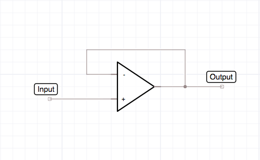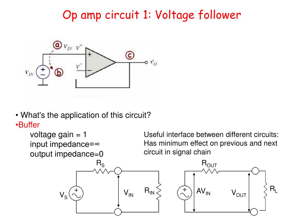
In theory, this impedance is equal to the open-loop input resistance (typically 1M0 in a bipolar 741) multiplied by A O/A. In Figure 3, the parallel values of R1 and R2 should ideally (for optimum biasing) have a value equal to the source resistance of the input signal.Ī major feature of the non-inverting op-amp circuit is that it gives a very high input impedance. Note that - for correct operation - the input (non-inverting) terminal of each of these circuits must be provided with a DC path to the common or zero-volts rail this path is provided by the DC input signal. Non-inverting variable gain (x1 to x101) DC amplifier. Non-inverting DC amplifier with offset-nulling facility and x10 gain.įIGURE 4. The gain can thus be made variable by replacing R1 with a pot and connecting its slider to the inverting terminal of the op-amp, as shown in the circuit in Figure 4, in which the gain can be varied over the range x1 to x101 via RV2.įIGURE 3. If R1 is given a value of zero, the gain falls to unity alternatively, if R2 is given a value of zero, the gain equals the open-loop gain of the op-amp. The voltage gain is determined by the ratios of R1 and R2, as indicated. NON-INVERTING AMPLIFIER CIRCUITSĪn op-amp can be used as a non-inverting DC amplifier with offset compensation by using the connections shown in Figure 3, which shows an x10 amplifier. Note in this case that no offset nulling facility is needed, and that (for optimum biasing) R3 is given a value equal to R2.
#VOLTAGE FOLLOWER OP AMP SERIES#
The Figure 1 circuit can be adapted for use as an AC amplifier by simply wiring a blocking capacitor in series with the input terminal, as shown in Figure 2. Note that the Figure 1 circuit will continue to function if the RV1 offset-nulling network is removed, but its output may offset by an amount equal to the op-amp’s input offset voltage (typically 1mV in a 741) multiplied by the closed-loop voltage gain (A) of the circuit, e.g., if the circuit has a gain of x100, the output may be offset by 100mV with zero input applied.Īlso note that the circuit’s bandwidth equals the f T value (typically 1MHz in a 741) divided by the ‘A’ value, e.g., the Figure 1 circuit gives a bandwidth of 100kHz with a gain of x10, or 10kHz with a gain of x100.įIGURE 2. Inverting DC amplifier with offset-nulling facility and x10 voltage gain. For optimum biasing stability, R3 should have a value equal to the parallel values of R1 and R2.įIGURE 1.


The gain can be made variable - if required - by using a series combination of a fixed and a variable resistor in place of R2. The voltage gain and input impedance are determined by the R1 and R2 values, and can be altered to suit individual needs.

INVERTING AMPLIFIER CIRCUITSįigure 1 shows the practical circuit of an inverting DC amplifier with an overall voltage gain (A) of x10 (= 20dB), and with an offset nulling facility that enables the output to be set to precisely zero with zero applied input. When reading this episode, note that all practical circuits are shown designed around a standard 741-type op-amp and operated from dual 9V supplies, but that these circuits will usually work (without modification) with most voltage-differencing op-amps, and from any DC supply within that op-amp’s operating range (allowing for possible differences in the op-amp’s offset biasing networks). This installment looks at practical ways of using such op-amps in linear amplifier and active filter applications. Our opening episode of this four-part ‘op-amp’ series described the basic operating principles of conventional voltage-differencing op-amps (typified by the 741 type) and showed some basic circuit configurations in which they can be used.


 0 kommentar(er)
